
Overview
Adjacent Satellite Interference (ASI) is a phenomenon that occurs when two or more satellite signals are received by a ground terminal (downlink ASI or dASI) or when two or more ground terminal signals are received by satellite (uplink ASI or uASI). The phenomenon is similar to two nearby radio stations broadcasting at the same frequency. The receiver, in this case, a radio, will toggle between both stations based on power fluctuation or play static which is a result of two signals interfering with each other.
This problem can only occur if the two satellites are operating in the same frequency band. Otherwise, much like how two radio stations at different frequencies don’t interfere with each other, the satellite will not see any overlapping signals.
Classifications
Downlink ASI
dASI is when the ground terminal’s receiver antenna has such a large effective “field-of-view” for incident beams that it can receive significant signal levels from satellites other than the one it is receiving from. For example, in the figure below, the Small Aero Antenna has a wide receiver beam width that can be traced to the two satellites on the right, as opposed to the Large Hub Antenna that has a narrow receiver beam width pointed at only one satellite, second from the left.
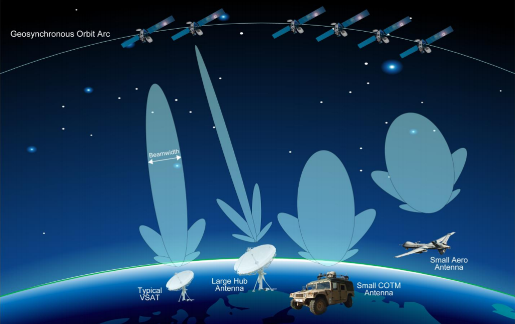
Intelsat General Corporation dASI figure; published March 12, 2015
Note that, in the picture above, the antennae are not uploading; they are downloading. The beamwidth shown is a downlink beam width, not an uplink beamwidth.
Uplink ASI
uASI is similar in that two adjacent satellites receive and then broadcast a signal from an antenna that is too narrow or wide in beamwidth, is pointed incorrectly, or is both at the same time. Consider the picture below. The network on the left has two antennas communicating with each other using one satellite. The network on the right has an antenna that is pointed such that its signal is transmitted to the satellite on the right (its network satellite) and the satellite on the left (an out-of-network satellite). The right network’s antenna’s signal interferes with the left network’s signals at the leftmost satellite, causing uASI.
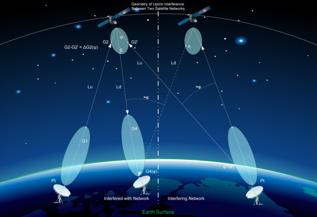
Intelsat General Corporation, uASI figure; published March 12, 2015
Causes and Variables Impacting Severity
Satellites that are very close together (within 2 to 4° of latitude/longitude) are more likely to experience ASI. As satellites come closer together, uplink and downlink beams have a higher chance of crosstalk. The chance of ASI increases if a smaller antenna is used since small antennae have wider beamwidths than larger antennae. In a given environment, many variables affect the severity of ASI:
- Satellite spacing: 2 to 4° of lat/longitude difference is where ASI begins. <2° nets an intense increase in ASI
- Frequency/Beam overlap with other satellites: determined primarily by beam width or how an antenna is positioned. The wider the beam width or the worse the positioning, the higher chance of ASI with a satellite out of the beam’s network.
- Ground terminal pointing angle: the worse a ground terminal is positioned toward a satellite, the higher chance there is of ASI.
- High Equivalent Isotropically Radiated Power (EIRP) in uASI: as the power outputted by a ground terminal increases, the chance of its signal being picked up by nearby satellites increases.
- Transponder sensitivity for uASI: the more sensitive a satellite is to incoming signals, the higher chance there is of it receiving even a small bit of crosstalk from another ground terminal.
Mitigation Techniques
Inter-Satellite Coordination
Satellite owners often work with adjacent satellites to coordinate uplink and downlink power density limits. Since areas around the globe have different levels of interference based on geography, population density, and climate, each area will contain a different limit on how much power density can be uploaded or downloaded. For example, in Karachi, West Pakistan, the power density limit is 3.2 dB to compensate for the immense amount of interference. In Saharan Africa, the power density limit is less than 1.5 dB so the uplink/downlink in that area doesn’t undergo saturation or ASI.
Satellite owners will also calculate expected ASI per area and will take steps to protect their ground terminals, such as limiting the size of the antenna. Another common practice is to put powerful transmitters in areas of high interference and lighter, less power-hungry transmitters in areas of lower interference for reasons similar to why the power density limit is high in Karachi and low in the Saharan Desert.
Satellite User Contribution
Satellite users can mitigate ASI by operating their satellites in certain ways. For example, by starting transmission in low power and slowly stepping up the power, ASI can be controlled. Users can also configure their terminals to stop broadcasting when a signal to a satellite is lost; this prevents crosstalk from occurring with another adjacent satellite, contributing to ASI. Users should monitor pointing errors and set a cut-off threshold if the antenna is throwing too many pointing errors.
By contacting the satellite owner for power limit, polarization, and pointing directions, users can mitigate ASI that could otherwise be caused by automatic signal acquisition software. This is an effective method for both accessing and disconnecting from a satellite.
For users transmitting in a mobile state, such as in a vehicle or plane, calibrating the IMU or coordinating antenna direction with vehicle direction will ensure a strong link. Fast or abrupt maneuvers in a plane can result in pointing errors or even signal loss. [1]
Unique Carrier Identification (CID)
Using a unique signal inside the carrier signal is a way to identify the source of a signal. CID acts like an electronic thumbprint that tells satellites where the signal is coming from, which can help eliminate ASI. However, since it is complex for satellite operators and terminal broadcasters to figure out which carrier is causing the interference, CID is still considered an emerging and improving technology. [2] The main strength of this technology is its capabilities for real-time ASI correction rather than pre-correction of commonly known problems like pointing, beamwidth, or excessive power density.
Related Links
Article: Overview, Classifications, Causes of ASI, and Mitigation Techniques